4 - PID Tuning
Tip
View the example project if you need more context for setup
Introduction
PIDs are used in the majority of motion algorithms in LemLib. There are 2 PID Controllers used by LemLib: one for lateral motion, and one for angular motion. This tutorial will focus on tuning those PIDs.
What is a PID?
See also
If you are not familiar with PID, check out the BLRS Wiki
A PID is a controller. It controls a mechanism. It takes a numerical input, and returns a numerical output. The numerical input is a measurement from a sensor, and the numerical output is the power for an actuator (e.g a motor).
Tuning a PID
Angular PID
Here is the PID settings we copy/pasted earlier:
lemlib::ControllerSettings angular_controller(2, // proportional gain (kP)
                                              0, // integral gain (kI)
                                              10, // derivative gain (kD)
                                              3, // anti windup
                                              1, // small error range, in inches
                                              100, // small error range timeout, in milliseconds
                                              3, // large error range, in inches
                                              500, // large error range timeout, in milliseconds
                                              0 // maximum acceleration (slew)
);
kP and kD
kP and kD is the most important settings, they are responsible for the majority of the movement. To tune them, we will start by disabling all other settings:
lemlib::ControllerSettings angular_controller(2, // proportional gain (kP)
                                              0, // integral gain (kI)
                                              10, // derivative gain (kD)
                                              0, // anti windup
                                              0, // small error range, in inches
                                              0, // small error range timeout, in milliseconds
                                              0, // large error range, in inches
                                              0, // large error range timeout, in milliseconds
                                              0 // maximum acceleration (slew)
);
We will use Chassis::turnToHeading to tune the angular controller:
void autonomous() {
    // set position to x:0, y:0, heading:0
    chassis.setPose(0, 0, 0);
    // turn to face heading 90 with a very long timeout
    chassis.turnToHeading(90, 100000);
}
To tune the PID, use this flowchart. Repeat until no amount of kD stops the robot from oscillating:

kI and Anti-Windup Range
Caution
kI should only be used as a last resort, when kP and kD can’t be tuned to a satisfactory degree, which is rare
Important
This needs to be done after tuning kP and kD
Important
All gains other than kP and kD should be disabled while tuning kI
Note
steady-state error is the distance between the robot and the target after the robot stops moving
kI is the integral gain. It’s used to correct steady-state error. This is usually used in velocity controllers and not positional controllers, but in some cases it is necessary for positional controllers.
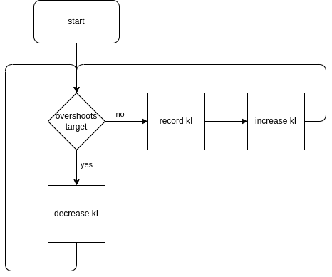
First, we need to determine the range of steady-state error after a motion. To do that, record the average steady-state error. To record the average steady state error, move the robot in motions between 10 degrees and 180 degrees and record the average steady-state error. Then increase that by 50%. This is the anti-windup range. Enter the new anti-windup range into the settings. But what is an anti-windup range? An anti-windup range is a range where the integral component of the controller can be increased. If error is outside of this range, integral will be set to 0. This is to prevent overshooting the target for long motions.
Now that we have the anti-windup range, we need to tune kI. Repeat the procedure below until satisfied:
When the procedure has been completed, enter your new kI gain.
Slew
Caution
It is extremely rare that angular acceleration needs to be limited. Skip this section unless you know what you are doing
Slew is used to limit angular acceleration. There aren’t really any situations where this is necessary except for extreme circumstances. For example: a 70lbs VEXU robot that will quickly burn out its motors if it accelerates too quickly.
A slew of 0 disables acceleration limiting. Higher values allow the robot to accelerate faster. For example, a value of 127 will allow the robot to accelerate to max velocity from rest in 10ms.
Since there is no use case for angular acceleration limiting except in extreme situations, this document will not cover tuning angular slew.
Lateral PID
Here is the PID settings we copy/pasted earlier:
lemlib::ControllerSettings lateral_controller(10, // proportional gain (kP)
                                              0, // integral gain (kI)
                                              3, // derivative gain (kD)
                                              3, // anti windup
                                              1, // small error range, in inches
                                              100, // small error range timeout, in milliseconds
                                              3, // large error range, in inches
                                              500, // large error range timeout, in milliseconds
                                              20 // maximum acceleration (slew)
);
kP and kD
kP and kD is the most important settings, they are responsible for the majority of the movement. To tune them, we will start by disabling all other settings:
lemlib::ControllerSettings lateral_controller(10, // proportional gain (kP)
                                              0, // integral gain (kI)
                                              3, // derivative gain (kD)
                                              0, // anti windup
                                              0, // small error range, in inches
                                              0, // small error range timeout, in milliseconds
                                              0, // large error range, in inches
                                              0, // large error range timeout, in milliseconds
                                              0 // maximum acceleration (slew)
);
To tune the PID, use this flowchart. Repeat until no amount of kD stops the robot from oscillating:
When this process is finished, use the found values in the settings and restore the disabled gains:
lemlib::ControllerSettings lateral_controller(10, // proportional gain (kP)
                                              0, // integral gain (kI)
                                              3, // derivative gain (kD)
                                              3, // anti windup
                                              1, // small error range, in inches
                                              100, // small error range timeout, in milliseconds
                                              3, // large error range, in inches
                                              500, // large error range timeout, in milliseconds
                                              20 // maximum acceleration (slew)
);
kI and Anti-Windup Range
Caution
kI should only be used as a last resort, when kP and kD can’t be tuned to a satisfactory degree, which is rare
Important
This needs to be done after tuning kP and kD
Important
All gains other than kP and kD should be disabled while tuning kI
Note
steady-state error is the distance between the robot and the target after the robot stops moving
kI is the integral gain. It’s used to correct steady-state error. This is usually used in velocity controllers and not positional controllers, but in some cases it is necessary for positional controllers.
First, we need to determine the range of steady-state error after a motion. To do that, record the average steady-state error. To record the average steady state error, move the robot in motions between 5” and 48” and record the average steady-state error. Then increase that by 50%. This is the anti-windup range. Enter the new anti-windup range into the settings. But what is an anti-windup range? An anti-windup range is a range where the integral component of the controller can be increased. If error is outside of this range, integral will be set to 0. This is to prevent overshooting the target for long motions.
Now that we have the anti-windup range, we need to tune kI. Repeat the procedure below until satisfied:
When the procedure has been completed, enter your new kI gain.
Slew
Note
Tuning slew is optional. It’s generally only used when using IMEs for tracking or when a robot tips easily
Important
Tuning slew should be done after tuning kP and kD
Slew limits how fast the robot can accelerate. This is useful when you are using internal motor encoders for position tracking, or if your robot tips easily.
A slew value of 0 disables it. Higher slew values let the robot accelerate faster. For example, a slew of 127 will let the robot go from rest to full speed in 10ms. To tune slew, you first need to identify why you need to tune it in the first place.
Preventing Wheel Slippage
If you do not have a vertical tracking wheel, you should use slew to prevent wheel slipping. Wheel slipping needs to be prevented so the position tracking can remain accurate. To tune slew in this scenario, select a high value for slew: 127. Then, use the code snippet below to move the robot 48” forwards (equivalent to 2 field tiles):
void autonomous() {
     // set position to x:0, y:0, heading:0
    chassis.setPose(0, 0, 0);
    // move 48" forwards
    chassis.moveToPoint(0, 48, 10000);
}
If you think the tracking could be more accurate, try decreasing slew and run the program again. Repeat until decreasing slew does not impact accuracy.
Preventing robot tipping
If you want to prevent the robot from tipping, you will need to tune slew. First, set slew to a high value: 127. Then, use the code snippet below to move the robot 48” forwards (equivalent to 2 field tiles):
void autonomous() {
     // set position to x:0, y:0, heading:0
    chassis.setPose(0, 0, 0);
    // move 48" forwards
    chassis.moveToPoint(0, 48, 10000);
}
Decrease slew to make the robot tip less. Run the program again and decrease slew until the robot no longer tips.
Exit Conditions
Exit conditions determine when motions will exit. Motions have 3 exit conditions:
Timeout
Short timeout when the robot is within a certain range of the target
Very short timeout when the robot is within certain small range of the target
The main timeout is used in case something unexpected happens, like when the robot collides with another robot. This allows the autonomous to continue to the next motion where it can potentially recover.
The other 2 timeouts are used when the robot is close to the target. There is a longer timeout and a shorter timeout. For example:
if the robot is within 5 inches of the target for 500ms, exit
if the robot is within 1 inch of the target for 100ms, exit
These exit conditions are tuned in the PID settings constructor. See the code example below:
lemlib::ControllerSettings lateral_controller(10, // proportional gain (kP)
                                              0, // integral gain (kI)
                                              3, // derivative gain (kD)
                                              3, // anti windup
                                              1, // small error range, in inches
                                              100, // small error range timeout, in milliseconds
                                              3, // large error range, in inches
                                              500, // large error range timeout, in milliseconds
                                              20 // maximum acceleration (slew)
);
You have now tuned the PIDs!